Installation
Video Tutorial
Before Installation
Prerequisites
- Thingsee Gateway is installed and operational (LED blinking green)
- Installation surface is clean and dry
- Plan sensor locations to maintain mesh network coverage
Network Coverage
- Maximum distance: 20m between sensors or to gateway
- Use intermediate sensors as routers for distances > 20m
- Account for signal attenuation from fire doors, thick walls, metal structures, and dense building materials
Sensor Capabilities
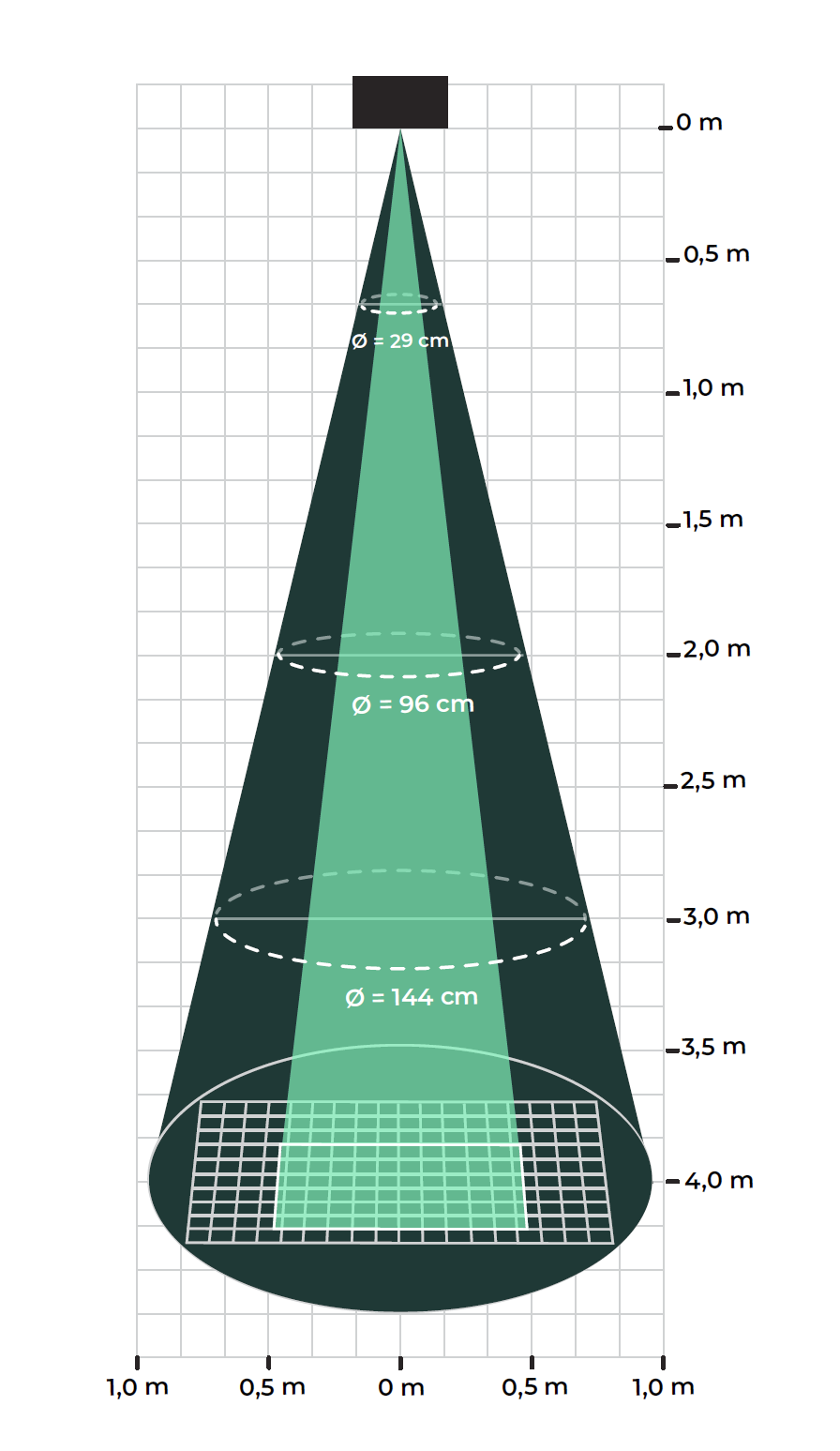
Thingsee BEAM measures the distance between the sensor and any solid surface using a Time-of-Flight (ToF) laser.
- Measurement range: 40–4000 mm
- Accuracy: ±25 mm (depends on ambient light and target reflectance)
- Beam width: 15–27° adjustable cone (Region of Interest)
- Class 1 laser: Safe under all conditions of normal use
Device Identification and Activation
Identify the Sensor
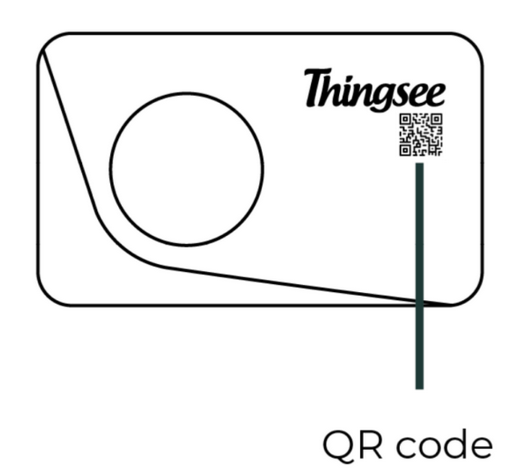
Read the QR code on the front of the device using a QR code reader or the Haltian Field application on your mobile device.
Activate the Sensor
The sensor ships with batteries pre-installed and a protective battery tab.
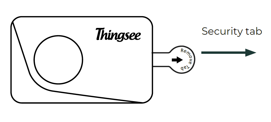
- Carefully pull out the battery security tab
- The LED indicator (red) will flash once to confirm activation
- If the LED doesn’t flash within 2 minutes, tap the sensor against your palm
- If the LED still does not flash, open the sensor and reinstall the batteries (see Battery Replacement)
Before mounting, verify that the installation location is within 20 m of the nearest Haltian device (sensor or gateway) to ensure mesh network connectivity.
Things to Avoid
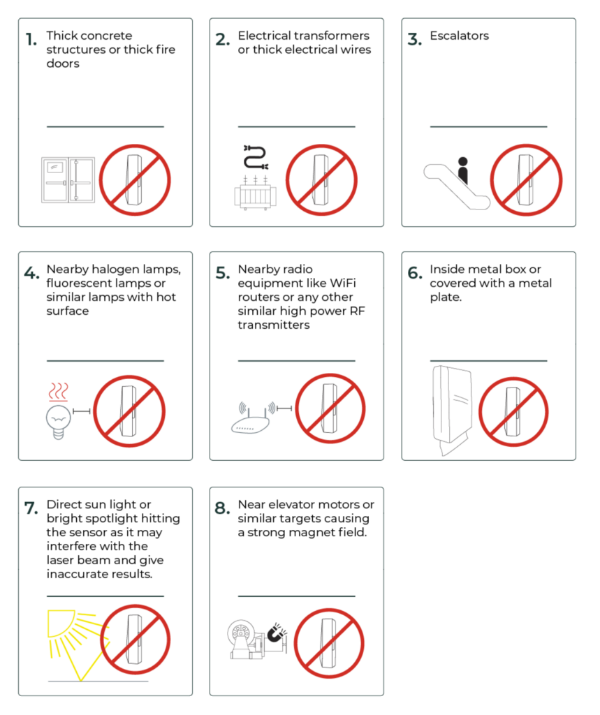
❌ Glossy or reflective surfaces (interfere with laser beam)
❌ Transparent surfaces (laser passes through)
❌ Dark, matte-black surfaces (low reflectance reduces range)
❌ Distance < 40 mm to measured surface
❌ Obstructions between sensor and measured surface
❌ Angles > ±6° from perpendicular
❌ Direct sunlight on the sensor lens
❌ Distance > 20 m to nearest sensor or gateway
Target Surface Requirements
✅ Works well with: solid, matte surfaces (paper, cardboard, wood), white or light-colored targets
❌ May cause issues: glossy/mirror-like surfaces, transparent materials (glass, clear plastic), very dark surfaces
Installation
General Placement Rules
- Install the sensor above or below the surface you want to measure
- Maintain at least 40 mm (4 cm) distance from the measured surface
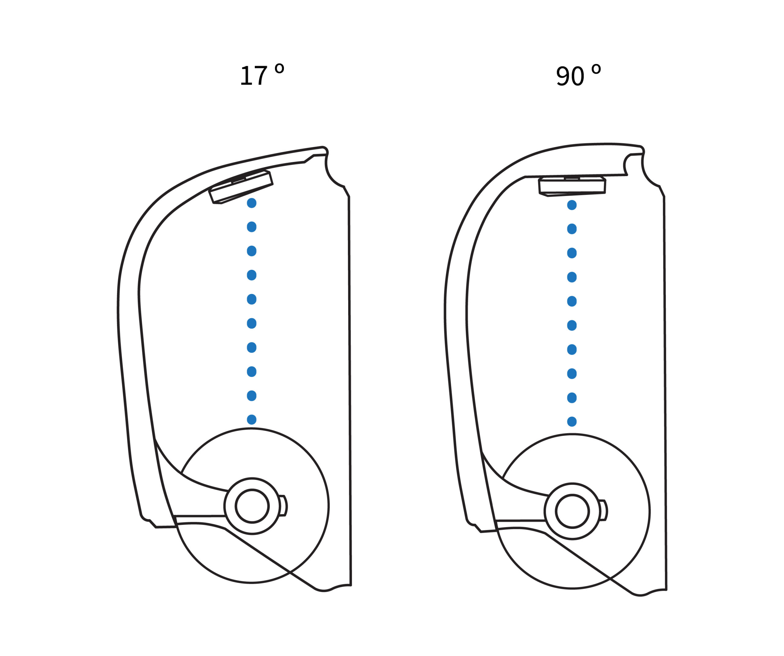
- The recommended angle between sensor and surface is 90°, adjustable by ±6° to either side
Mounting
- Clean the surface: Wipe the installation surface with IPA solvent (isopropyl alcohol) and allow to dry
- Remove the tape backing from the backside of the sensor
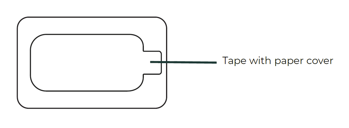
- Attach the sensor by pressing it firmly against the surface for a minimum of 5 seconds
- Wipe the sensor lens with a clean cloth
Install the sensor max. 20 meters from the next sensor or gateway to ensure full mesh network coverage.
Placement by Use Case
Dispenser Fill-Level Monitoring
Install the sensor above or below the consumable material inside the dispenser. The laser beam should point at the top surface of the material (e.g., paper towels, soap level).
- Position sensor so the beam hits the consumable surface directly
- As material is consumed, the distance increases — this indicates fill level dropping
- Ensure no moving parts or covers obstruct the beam path
Trash Bin Fill-Level Monitoring
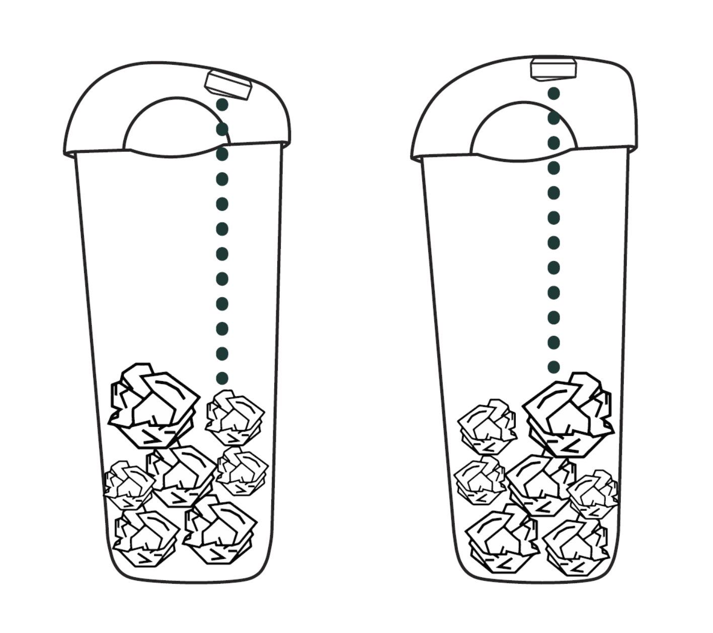
Install the sensor above the trash inside the bin, pointing downward.
- Ensure the plastic bag (if used) is not in the sensor beam area
- The sensor must have a clear line of sight to the trash without disturbances
- If the bin has only a partial lid, the sensor can be installed on the side, as long as the beam reaches the trash inside
- As the bin fills, the measured distance decreases
The sensor tolerates a tilt of up to ±6° from perpendicular — useful when mounting on angled or curved bin lids.
Shelf Fill-Level Monitoring
Place the sensor above and next to the monitored objects so that the sensor beam is pointing at the objects.
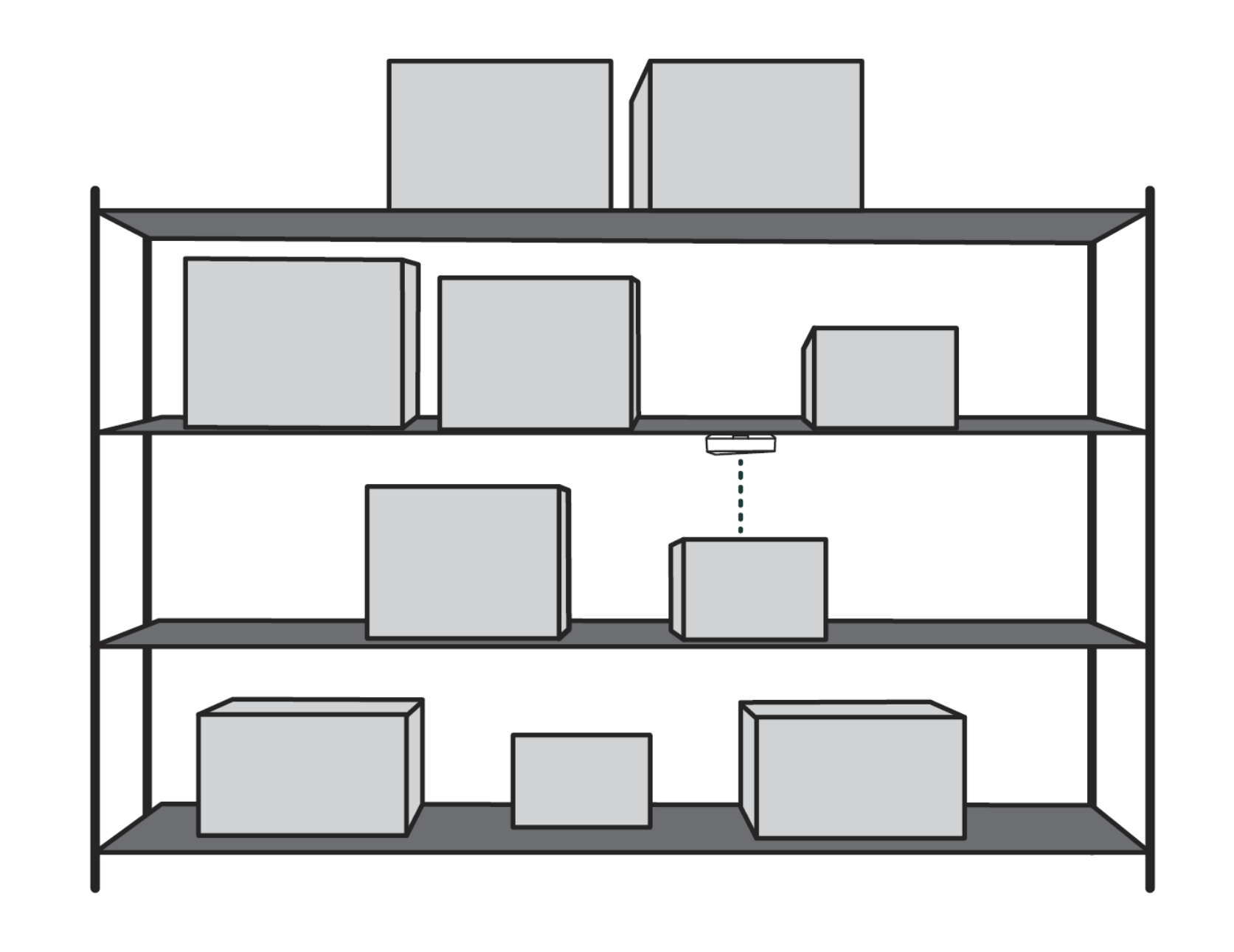
- Position so the beam measures the height or depth of stacked items
- As items are removed, the measured distance increases
Battery Replacement
The sensor uses 2× AAA alkaline batteries. Recommended: Varta Industrial Pro 1.5V AAA LR03. Do not use lithium or rechargeable NiMH batteries.
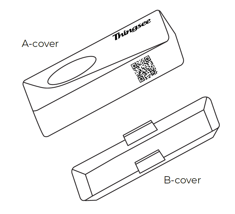
When Holding the Sensor in Hand
- Insert the opening key in the hole on the side of the sensor and twist to open
- Separate the A-cover from the B-cover
- Place the batteries inside the A-cover, observing correct polarity
- Attach the A-cover to the B-cover (Thingsee logo upright) and press until it clicks
When the Sensor is on the Installed Surface
- Insert the opening key in the side hole and twist to release the A-cover
- Pull the A-cover away from the B-cover (B-cover remains on the surface)
- Remove old batteries and insert fresh AAA batteries, matching polarity
- Reattach the A-cover and press until it clicks securely
The device will rejoin the network automatically after battery replacement. Wait up to 10 minutes for the first data to appear.
Post-Installation Verification
Network Connection
- Wait for network join — the device automatically joins the Wirepas mesh network (typically 1–5 minutes, up to 10 minutes)
- Verify in the Haltian application — confirm the sensor appears in the device list with a recent “Last Seen” timestamp
Initial Data
- Distance readings should appear within 5–10 minutes
- Verify the measured distance is reasonable for the installation (matches actual distance to target surface)
Signal Strength
Verify signal strength is acceptable (RSSI > -85 dBm) in the Haltian application. If signal is poor, add an intermediate sensor as router, reposition closer to the gateway, or check for physical obstructions.
For detailed RSSI ranges and network troubleshooting, see Operation — Network Health Monitoring.
Installation Checklist
- Gateway operational and connected
- Sensor identified (QR code scanned with Haltian Field)
- Battery tab pulled, LED confirmed
- Surface cleaned with IPA
- Sensor mounted with clear line of sight to target surface
- Minimum 40 mm distance to target
- Sensor within 20 m of nearest sensor or gateway
- Sensor appears in the Haltian application
- Distance readings received and reasonable
- Signal strength acceptable (RSSI > -85 dBm)