Installation
Video Tutorial
Before Installation
Prerequisites
- Thingsee Gateway is installed and operational (LED blinking green)
- Installation surface is clean and dry
- Plan sensor locations to maintain mesh network coverage
Network Coverage
- Maximum distance: 20m between sensors or to gateway
- Use intermediate sensors as routers for distances > 20m
- Account for signal attenuation from fire doors, thick walls, metal structures, and dense building materials
Sensor Capabilities
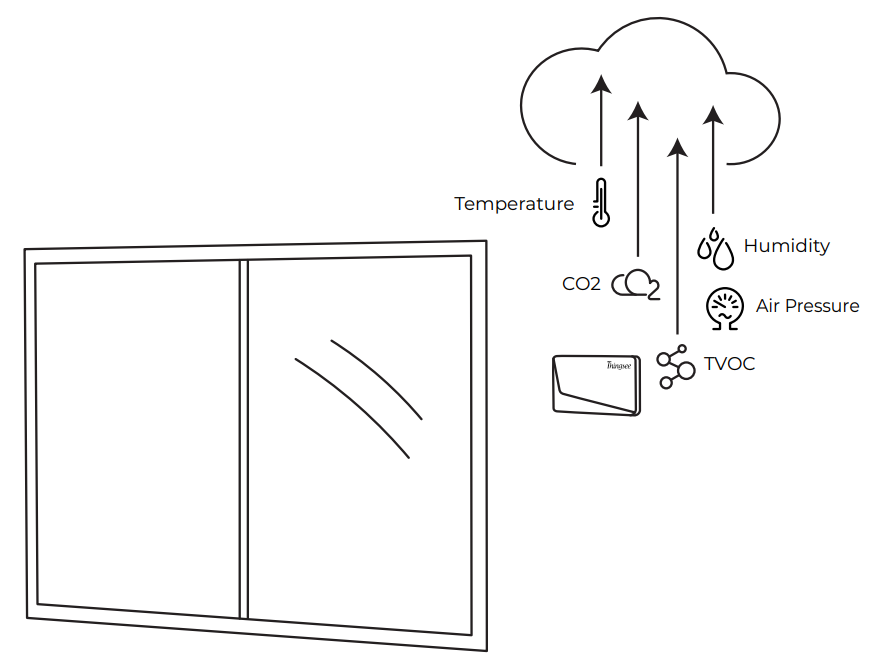
Thingsee AIR measures CO₂, TVOC, temperature, humidity, and barometric pressure.
Baseline Calibration
Thingsee AIR requires an initial calibration period for accurate readings:
- TVOC sensor: Valid data available after 48 hours of continuous use
- CO₂ sensor: Baseline optimization updated in 8-day periods, adjusting toward a preconfigured 410 ppm CO₂ level
The sensor requires “free of people” moments when indoor air is fully exchanged to set the correct 410 ppm baseline. Spaces such as offices and schools are ideal, as the baseline can be set during the night when CO₂ is lowest. Continuously occupied spaces (24/7) are not recommended.
Device Identification and Activation
Identify the Sensor
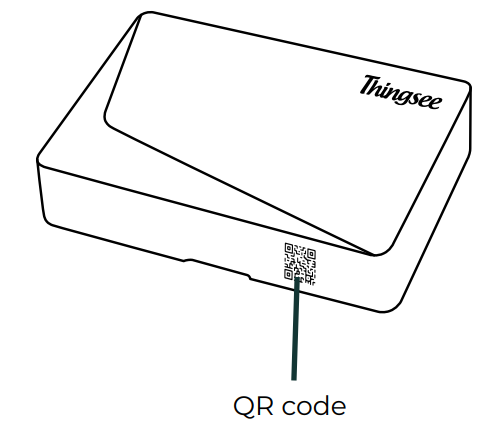
Read the QR code on the side of the A-cover using a QR code reader or the Haltian Field application on your mobile device.
Open the Device
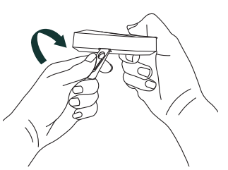
Use the opening key to separate the A-cover from the B-cover.
Install Batteries
Place 2x AA alkaline batteries inside the A-cover. Recommended: Varta Industrial Pro 1.5V AA LR06.
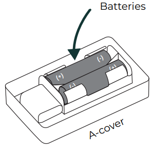
The LED will flash to confirm power-on. If no flash, check battery polarity.
Things to Avoid
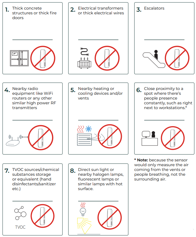
❌ Direct sunlight or near large windows
❌ Near heating radiators or cooling vents
❌ Corners with poor air circulation
❌ In direct ventilation airflow
❌ Near TVOC sources (hand sanitizer dispensers, cleaning chemicals)
❌ Near WiFi routers or high-power RF transmitters
❌ Near halogen or fluorescent lamps with hot surfaces
❌ Near electrical transformers or escalators
❌ Distance > 20m to nearest sensor or gateway
Choosing the Installation Spot
Install the sensor at 1.4–1.8 m height on a wall where it represents the general air quality of the room. The placement diagrams below show recommended positions (green) and positions to avoid (red).
Rooms with Air Conditioning
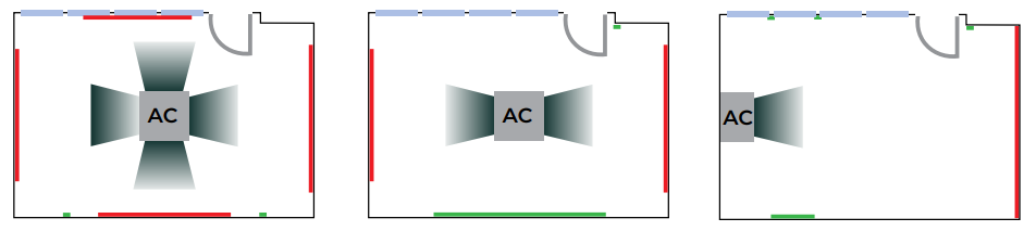
Install on the wall opposite to the AC unit, at least 2m away from direct airflow.
Avoid Corners
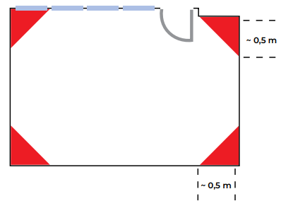
Keep at least 0.5m from corners — air circulation is poor in corner positions.
Rooms with Large Windows
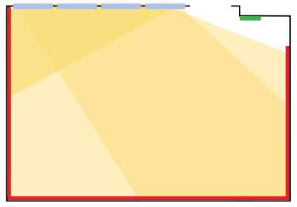
Install on an interior wall, away from direct sun exposure and window drafts.
Rooms with Heating Radiators
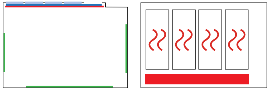
Install on the opposite wall from the radiator, at least 1.5m away from the heat source.
Large Open Office Spaces
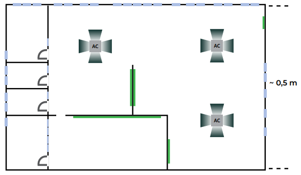
Use multiple sensors distributed evenly. Avoid placing only near external walls.
Air Ventilation
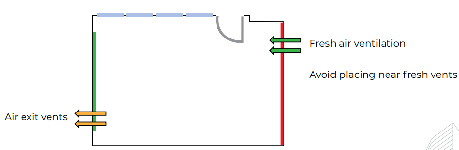
Install away from intake and exhaust vents. The sensor should measure room air, not supply air.
Installation Methods
Method 1: Tape Installation
Use a smooth surface for better adherence. Clean the surface with IPA solvent (isopropyl alcohol).
The marks on the back of the sensor work as guidelines for tape placement.
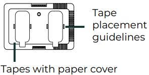
- Apply the tapes on the B-cover, pressing for a minimum of 5 seconds
- Remove the tape backing paper
- Position the B-cover at the desired height (1.4–1.8 m)
- Press firmly against the surface for a minimum of 5 seconds
Method 2: Screw Installation
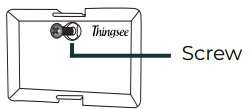
- Place the B-cover on the wall at the desired location
- Screw the B-cover to the wall (use an anchor for concrete or gypsum board)
- Verify the B-cover is level and does not wobble
Completing the Installation
After mounting the B-cover, attach the A-cover (with batteries installed):
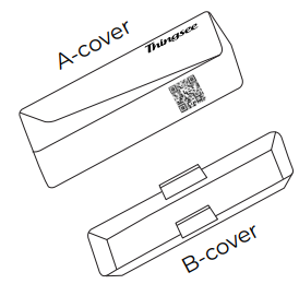
- Align the A-cover with the B-cover (Thingsee logo right-side up)
- Press the covers together until they click securely
- Verify no gaps between the covers
Install the sensor max. 20 meters from the next sensor or gateway to ensure full mesh network coverage.
Battery Replacement
The sensor uses 2x AA alkaline batteries. Recommended: Varta Industrial Pro 1.5V AA LR06. Do not use lithium or rechargeable NiMH batteries.
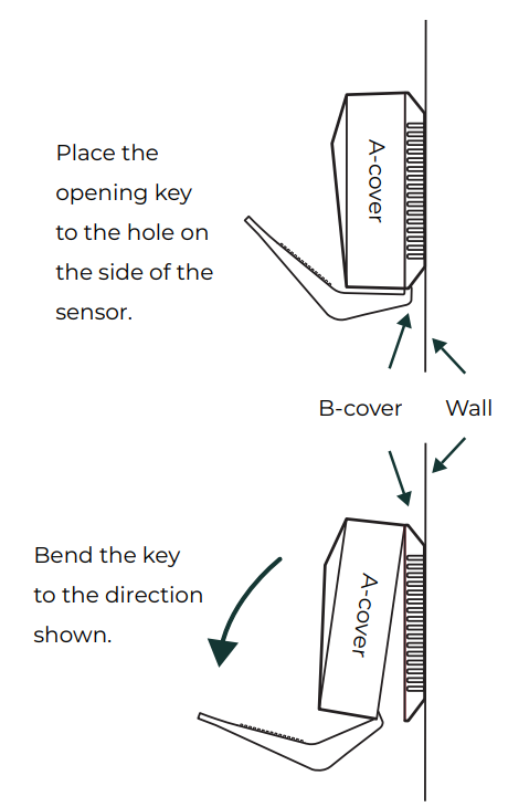
When the Sensor is on the Wall
- Insert the opening key in the side hole and twist to release the A-cover
- Pull the A-cover away from the B-cover (B-cover remains on the wall)
- Remove old batteries and insert fresh AA batteries, matching polarity
- Reattach the A-cover and press until it clicks securely
The device will rejoin the network automatically after battery replacement. Wait up to 10 minutes for the first data to appear.
Post-Installation Verification
Network Connection
- Wait for network join — the device automatically joins the Wirepas mesh network (typically 1–5 minutes, up to 10 minutes)
- Verify in the Haltian application — confirm the sensor appears in the device list with a recent “Last Seen” timestamp
Initial Data
- CO₂ and temperature readings should appear within 5–10 minutes
- TVOC requires 48 hours for valid baseline data
- CO₂ baseline adjusts toward 410 ppm over the first 8 days
Signal Strength
Verify signal strength is acceptable (RSSI > -85 dBm) in the Haltian application. If signal is poor, add an intermediate sensor as router, reposition closer to the gateway, or check for physical obstructions.
For detailed RSSI ranges and network troubleshooting, see Operation — Network Health Monitoring.
Installation Checklist
- Gateway operational and connected
- Sensor identified (QR code scanned with Haltian Field)
- Batteries installed, LED confirmed
- Surface cleaned with IPA
- Sensor mounted at 1.4–1.8 m height
- Sensor within 20m of nearest sensor or gateway
- Away from TVOC sources, vents, and heat sources
- Sensor appears in the Haltian application
- Initial readings received
- Signal strength acceptable (RSSI > -85 dBm)
- Calibration period noted (48h TVOC, 8 days CO₂)