Installation
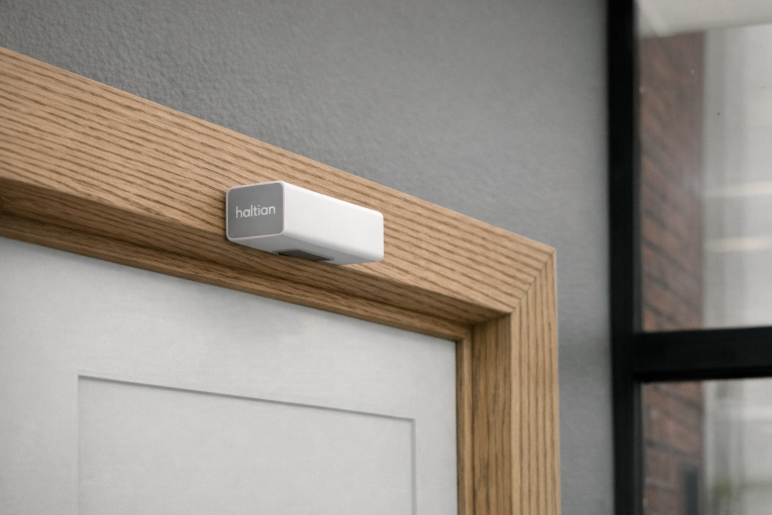
Haltian ENTRYWAY installed above a doorframe
Quick Reference
Use this section as an on-site checklist. For detailed instructions, continue to the relevant installation method below.
These rules are mandatory for all doorframe installations. Violating any rule will degrade counting accuracy or cause false counts.
- Maximum 1 cm from doorframe edge — The sensor must be flush with the bottom edge of the doorframe. A gap larger than 1 cm shifts the detection zone.
- Never install on the door-swing side — Mount the sensor on the opposite side from where the door opens. Door movement triggers false counts.
- Ceiling: minimum 1 meter from obstructions — When ceiling-mounted, the sensor must be at least 1 meter from any doorframe, wall, or beam.
Installation Checklist
Pre-Installation:
- Gateway operational and network ready
- Passageway width ≤ 1600mm, height 2200–2800mm
- Installation method selected (see table below)
- Mounting hardware ready (screws/anchors or tape)
During Installation:
- Device powered on (LED shows green = connected)
- Sensor securely mounted
- ⚠️ Sensor gap from doorframe bottom ≤ 1 cm (measure and verify)
- ⚠️ Sensor is NOT on the door-swing side (open the door to confirm)
- ⚠️ Ceiling mount: at least 1 meter from any wall, doorframe, or beam
- Entry direction configured (default or custom via Haltian support)
Post-Installation Verification:
- Device appears in Haltian Studio (~5 minutes)
- Empty passageway shows no false detections
- Walking through increments entry/exit counts correctly
- Signal strength acceptable (RSSI > −85 dBm)
Choose Your Installation Method
| If your location has… | Use | Go to |
|---|---|---|
| A doorframe (most common) | Method 1: Doorframe | Jump to Method 1 |
| A corridor or hallway without a doorframe | Method 2: Ceiling | Jump to Method 2 |
Before Installation
Prerequisites
- Ensure Thingsee Gateway is installed and operational
- Plan sensor locations to maintain mesh network coverage (< 20m between nodes)
- Identify doorways, corridors, or passages to monitor
- Measure passageway width and height
- Verify installation surface suitable for chosen mounting method
Planning Sensor Placement
Sensor placement on doorframe
Key Considerations:
- Maximum passageway width: 1600mm (1.6 meters)
- Maximum passageway height: 2800mm (2.8 meters)
- Recommended installation height: 2500mm from floor
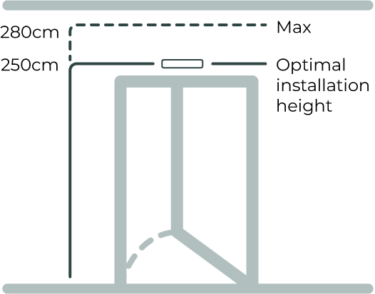
Recommended installation height: 2500mm from floor
- Direction configuration: Determined during installation (which side is “entry”)
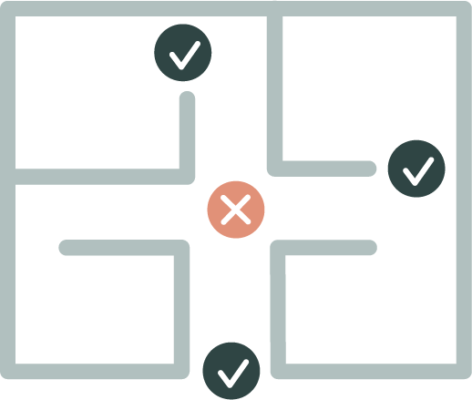
Passageway Suitability
Ideal passageways:
- Interior doorways (office-to-lobby, hallway-to-meeting room)
- Corridor bottlenecks (natural traffic flow points)
- Passage points between functionally distinct spaces
- Doorframes guiding people through defined path
Unsuitable locations:
- Wide-open entry zones (people side-by-side)
- Areas where people change direction abruptly
- Spaces where people linger unpredictably
Network Coverage Planning
- Maximum distance: 20m between sensors or to gateway
- Use intermediate sensors as routers for distances > 20m
- ENTRYWAY sensors work indoors only (0-50°C, 8-90% RH)
- Plan mesh topology for reliable data transmission
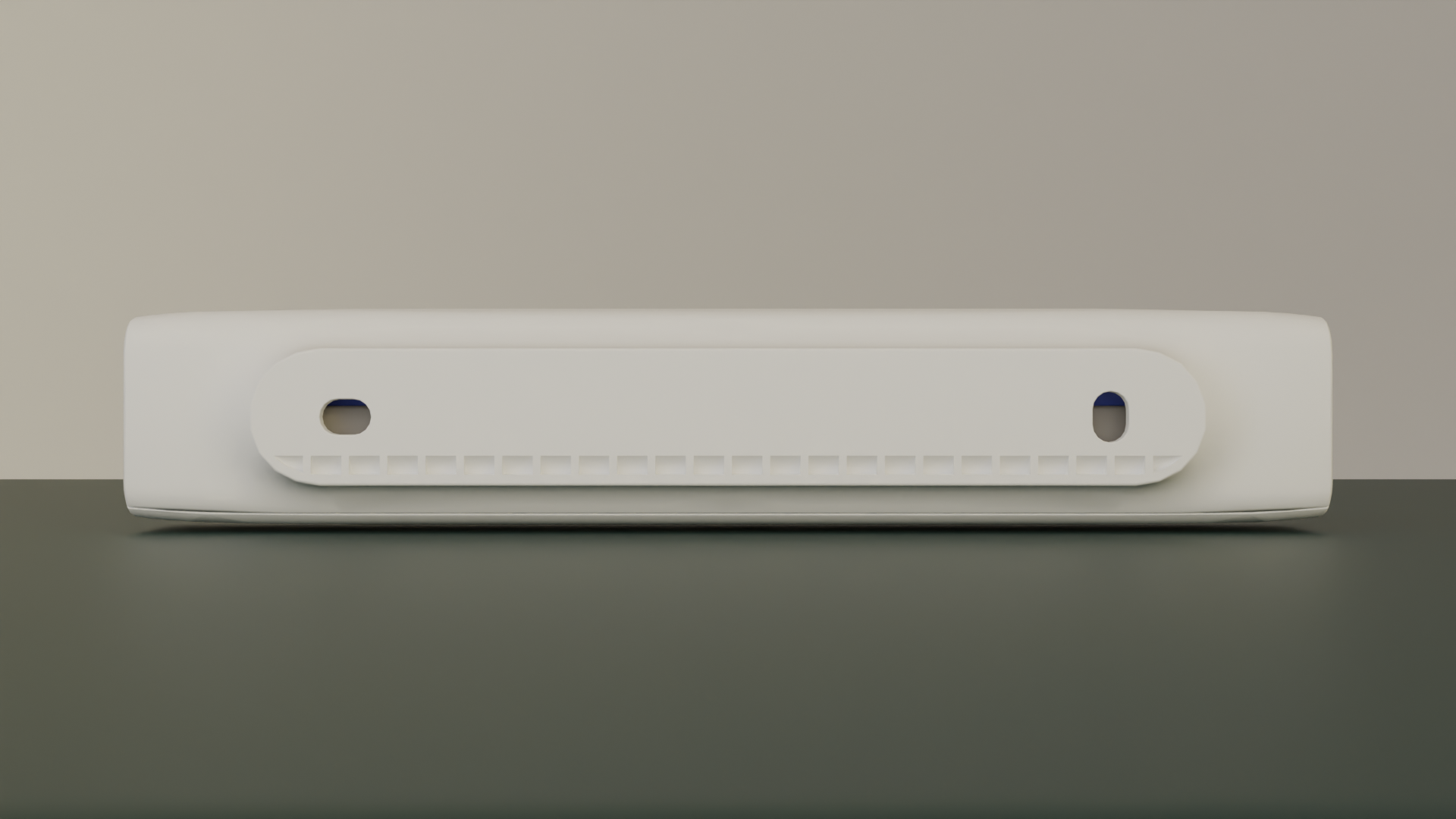
Power On Device
Power on the device by pressing the power button. The device comes with pre-installed batteries - no need to remove any battery slips.
To power on:
- Locate the power button on the sensor
- Press and hold the power button
- Observe the LED indicator
- LED will blink yellow for 3 seconds (power up confirmation)
- LED will continue blinking yellow while connecting to network
- LED shows solid green for 3 seconds when connection successful
LED Indicator Status
The LED provides visual feedback during power-up and network connection:
| Mode | LED Color | Description |
|---|---|---|
| Deep sleep | No LED | No LED indication |
| Power up (long button press) | 🟡 Yellow | LED blinks for 3 seconds |
| Connecting to network | 🟡 Yellow | LED blinks brightly with one-second interval until ready |
| Connection OK | 🟢 Green | LED shows bright for 3 seconds |
| Connection failed | 🔴 Red | LED blinks brightly and fast 3 times |
| Power off (long press) | 🔴 Red | LED shows bright for 3 seconds |
If you see red LED blinking fast 3 times, the sensor failed to connect to the network. Check that:
- Gateway is operational and within range (< 20m)
- No physical obstructions blocking signal
- Other sensors in mesh network are functioning
Common Installation Steps
All installation methods follow these core steps. Specific positioning requirements are detailed in each method below.
Choose Mounting Method
Select your mounting method based on the installation surface and whether the sensor may need to be relocated in the future.
Mounting Method Comparison: Tape vs. Screws
| Criteria | Tape mounting | Screw mounting |
|---|---|---|
| Typical use | Fast installation on smooth, non‑structural surfaces | Secure installation on structural surfaces |
| Recommended surfaces | Glass, metal panels | Wood, drywall, concrete/brick (with anchors) |
| Installation effort | Very fast, no drilling | Requires drilling |
| Holding strength | Very high on smooth surfaces (industrial‑grade adhesive tape) | Very high (mechanical fixing) |
| Surface requirements | Clean, dry, smooth surface | Surface must allow drilling |
| Surface impact on removal | High risk — adhesive may pull paint or surface coating off | Low to moderate — screw holes can be patched |
| Suitability for relocation | Poor | Good |
| Typical limitation | Removal can cause visible surface damage on some materials | Not suitable for glass |
Surface Recommendations
- Glass → Tape mounting (recommended)
- Metal → Tape mounting (recommended)
- Wood → Screw mounting (recommended)
- Drywall → Screw mounting (recommended)
- Concrete / brick → Screw mounting (with anchors)
If there is a possibility that the sensor will be relocated in the future, screw mounting is recommended, regardless of surface material. Repairing screw holes is typically easier than repairing surface damage caused by removing industrial‑grade adhesive tape.
Mount Sensor
Mounting options: screw or double-sided tape
Both mounting methods work well. Use tape when you want a quick, clean install with no drilling. Use screws when you expect to move the sensor later, or when the surface finish is sensitive — tape’s strong bond can lift paint or coating on removal.
Screw mounting:
- Drill pilot holes at marked positions (for concrete/brick: insert anchors; for wood: pilot holes sufficient)
- Align sensor with holes
- Insert screws through mounting holes in C-cover
- Tighten securely — do not over-tighten (plastic housing)
Tape mounting:
- Clean surface thoroughly with an alcohol wipe — ensure dry and dust-free
- Temperature must be above 10°C for proper adhesion
- Apply 3M VHB double-sided tape to the back of the sensor
- Remove the protective liner
- Position sensor precisely — tape bonds immediately on contact
- Press firmly for 10 seconds
- Wait 24 hours for full bond strength before testing
Note: 3M VHB tape creates a very strong bond — that’s what makes it reliable long-term. If you ever need to relocate the sensor, use a thin plastic card or dental floss to separate the tape slowly from the surface, and apply adhesive remover to clean the residue. Pulling straight off may damage the surface finish.
Configure Entry Direction
Default configuration:
- Entry direction: toward sensor when Haltian logo is on left side
- Exit direction: away from sensor
Entry direction arrow
If different direction needed:
To change the entry direction, open the Haltian Field application and navigate to the device details view — for example by scanning the device QR code. Open the configuration view and select the desired entry direction. For more details, see the Field application documentation.
Verify Installation
Verify using Haltian Studio or Haltian Field app (within 5 minutes):
Both applications show the device details view with the latest measurements. Open the device details for your sensor and confirm:
- Device appears in the device list
- Walk through entry direction — “entries” count increments
- Walk through exit direction — “exits” count increments
- Check signal strength (RSSI > −85 dBm recommended)
On-site checks:
- Sensor secure and level
- No obstructions in detection zone (lights, equipment, decorations)
- Door (if present) does not interfere when opening/closing
Installation Method 1: Doorframe
Haltian ENTRYWAY installed above a doorframe
Most common and recommended installation method
Requirements
- Location: Middle of doorframe
- Position: Device flush with bottom edge of doorframe
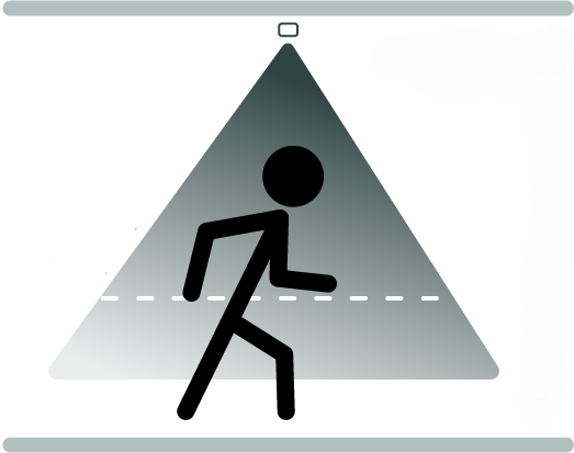
- Detection area: At least 10 cm from device to top of detection zone
The sensor must be mounted within 1 cm of the bottom edge of the doorframe. A gap larger than 1 cm misaligns the detection zone and will reduce counting accuracy. If you cannot achieve this clearance, choose a different mounting method.
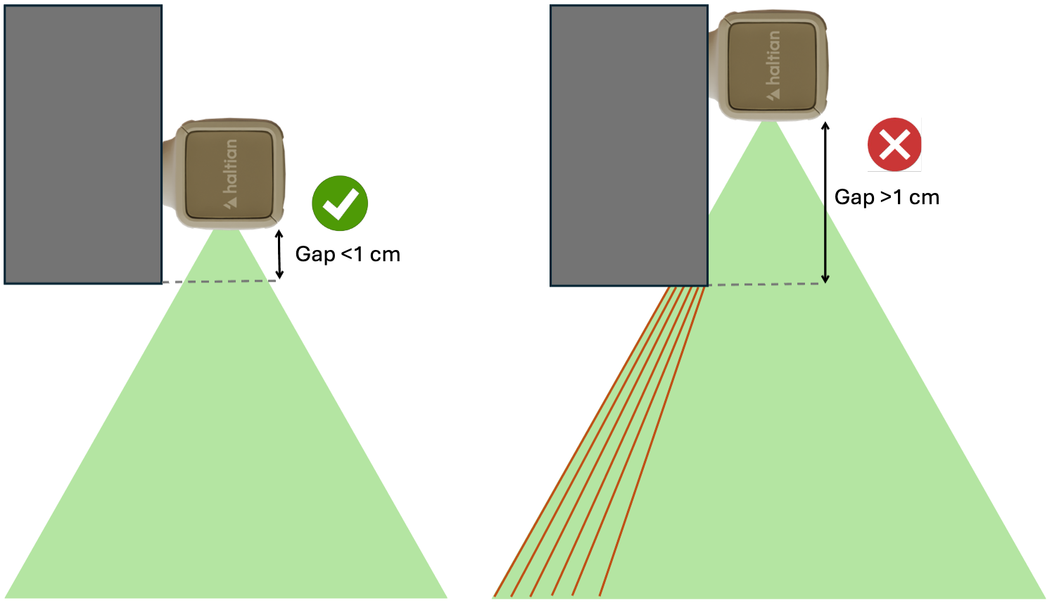
The sensor must sit flush with the doorframe bottom. Any gap allows the frame to cut the detection beam, causing missed or false counts.
The sensor must be installed on the opposite side from where the door opens. If the door swings toward the sensor, the door movement will be detected as people passing and will generate false entry/exit counts.
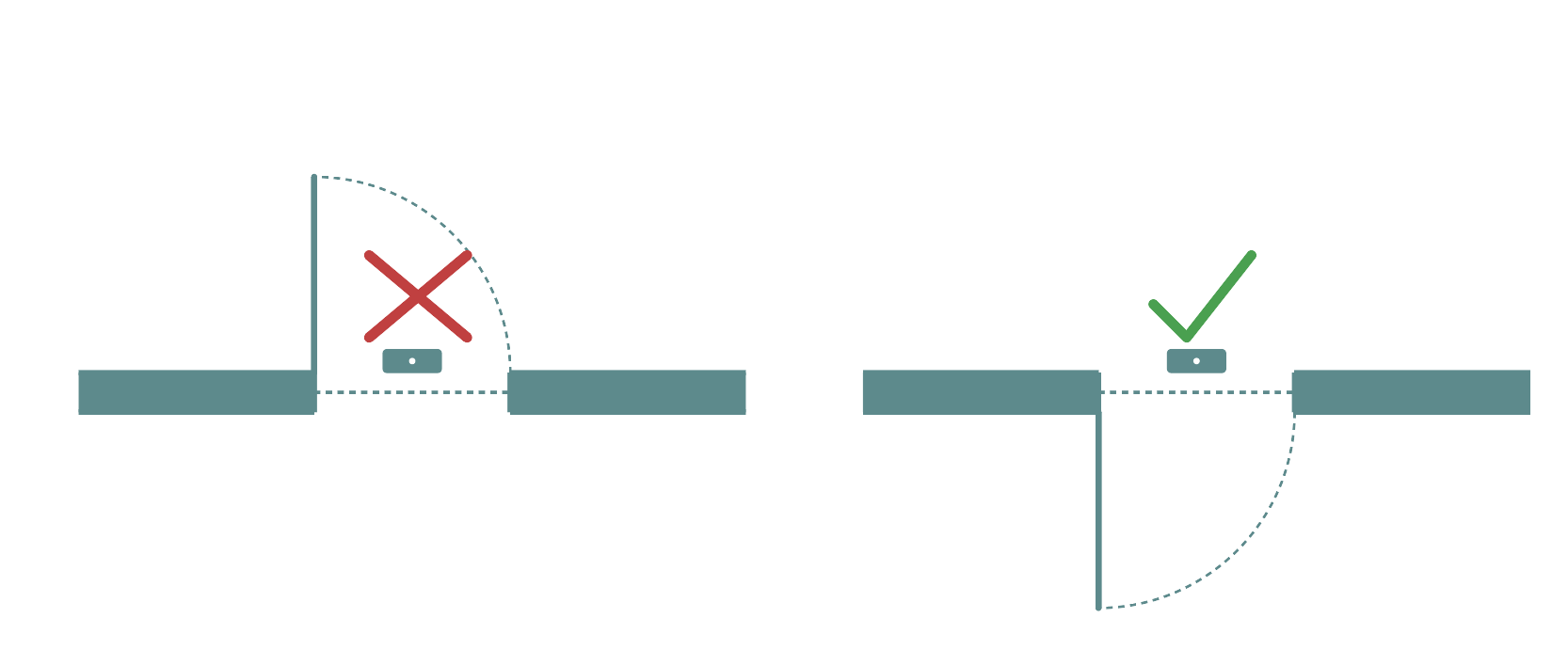
Always mount the sensor on the side opposite to the door swing direction
Step-by-Step Installation
1. Select Installation Position
- Identify center of doorframe (width-wise)
- Ensure doorframe at least 2200mm high (2500mm recommended)
- Verify doorframe width ≤ 1600mm
- Confirm the door opens away from the sensor side — if the door swings toward the planned position, move to the other side of the doorframe
2. Mark Mounting Position
- Hold sensor at center of doorframe
- Bottom of sensor flush with bottom edge of doorframe — maximum 1 cm gap allowed
- Sensor oriented so Haltian logo is on left side (default entry direction)
- Mark screw holes or tape position with pencil
3. Install the Sensor
Follow the Common Installation Steps above for:
- Preparing the surface (screw or tape)
- Mounting the sensor securely
- Configuring entry direction
- Verifying installation in Haltian Studio
Critical final checks for doorframe installation:**
- Sensor flush with doorframe bottom (maximum 1 cm gap) — re-mount if gap exceeds 1 cm
- Sensor centered (equal distance from both sides of doorframe)
- Door does not swing toward the sensor — open and close door fully to confirm
Key Tips for Doorframe Installation
✅ Always install on the side opposite the door swing — door movement will trigger false counts
✅ Measure the gap with a ruler — even 2 cm will reduce accuracy
✅ For heavy doors, verify door doesn’t vibrate the doorframe when closing
Installation Method 2: Ceiling Installation
Ideal for hallways and corridors without doorframes
Requirements
- Location: Middle of hallway ceiling
- Corridor width: Maximum 1600mm (1.6 meters)
- Ceiling height: 2200-2800mm recommended
- Foot traffic: Consider general traffic direction
When mounting on the ceiling, the sensor must be at least 1 meter away from any doorframe, wall edge, beam, or other overhead structure. Objects closer than 1 meter can partially block the downward detection beam, causing missed or inaccurate counts.
Ceiling installation: mount in the center of the corridor, at least 1 meter from any wall or obstruction
Step-by-Step Installation
1. Select Installation Position
- Identify center of corridor (width-wise)
- Choose position with predictable foot traffic flow
- Measure ceiling height (should be 2200-2800mm)
- Verify corridor width ≤ 1600mm
- Verify at least 1 meter clearance from any doorframe, wall edge, beam, or overhead structure that could block the detection beam
2. Mark Mounting Position
- Mark center point on ceiling
- Sensor orientation: Haltian logo on left for default entry direction
- Mark screw holes or tape position
3. Install the Sensor
Follow the Common Installation Steps above for:
- Preparing the ceiling surface (screw or tape - screw recommended for ceilings)
- Mounting the sensor securely
- Configuring entry direction
- Verifying installation in Haltian Studio
Critical final checks for ceiling installation:**
- Sensor centered on corridor
- At least 1 meter clearance from any wall, doorframe, beam, or overhead structure
- Sensor secure and cannot rotate
4. Verify Complete Installation
- Sensor centered on corridor
- Secure mounting (no rotation or sagging)
- Clear line of sight to floor
- No doorframe, wall, beam, or structure within 1 meter of the sensor in any direction
- Optimal for corridors ≤ 1600mm width
Key Tips for Ceiling Installation
✅ Always verify 1 meter clearance — use a measuring tape to confirm distance from walls and beams
✅ For drop ceilings, mount to structural support, not just the acoustic tile
✅ Consider pendant lights and signs — they can obstruct the detection beam
Post-Installation Verification
Network Connection
Wait for network join:
- Device automatically joins Wirepas mesh network
- Typical join time: 1-10 minutes
- May take longer in sparse mesh environments
Verify in Haltian Studio:
- Log into Haltian Studio application
- Navigate to device list
- Confirm sensor appears with correct ID
- Check “Last Seen” timestamp
Detection Testing
Entry Test
- Walk through passageway in entry direction:
- Default: Towards sensor (Haltian logo on left)
- Or configured direction (if custom)
- Complete full passage (walk through all three PIR beam sectors)
- Wait 30 seconds (measurement interval)
- Check Haltian Studio for “entries” count increment
Exit Test
- Walk through passageway in exit direction:
- Default: Away from sensor
- Or configured direction (if custom)
- Complete full passage (walk through all three PIR beam sectors)
- Wait 30 seconds (measurement interval)
- Check Haltian Studio for “exits” count increment
Directional Verification
- Entry direction test:
- Walk through in entry direction
- Verify “entries” increments, “exits” does not
- Exit direction test:
- Walk through in exit direction
- Verify “exits” increments, “entries” does not
- If incorrect:
- Contact Haltian support to reverse direction configuration
Repeat Testing
- Test 5-10 times to verify consistent detection
- Vary walking speed (slow, normal, fast)
- Test with different people (height, clothing variations)
Signal Strength Check
Review RSSI values in Haltian Studio:
- Good signal: > -70 dBm
- Acceptable: -70 to -85 dBm
- Poor: < -85 dBm
If signal poor:
- Add intermediate sensor as router
- Relocate gateway closer
- Check for RF obstructions (metal structures)
Mounting Hardware and Tools
Included in Package
- Haltian ENTRYWAY sensor (with 2× AA batteries installed)
- C-cover (mounting bracket)
- Mounting tape (double-sided adhesive)
- 2× screws
- 2× screw anchors (for concrete/brick)
Additional Tools Needed
For screw mounting:
- Drill (for pilot holes in concrete/brick/wood)
- Appropriate drill bit (size depends on wall material)
- Screwdriver (Phillips or flathead, depending on screw type)
- Level (to ensure sensor alignment)
- Pencil (to mark mounting positions)
For tape mounting:
- Alcohol wipes (to clean surface)
- Level (for alignment)
- Temporary support (for ceiling installations)
For ceiling mounting (additional):
- Drywall anchors or toggle bolts (if drywall ceiling)
- Ladder or lift (for access)
Weatherproofing (Indoor Use Only)
- ENTRYWAY operates indoors only (0-50°C, 8-90% RH)
- No additional weatherproofing needed for indoor installation
- Do not install outdoors (not IP-rated for outdoor use)
Common Installation Mistakes
Mistake 1: Passageway Too Wide
Problem: Passageway > 1600mm width
Impact: Detection accuracy decreases, multiple people side-by-side cause missed counts
Solution: Choose narrower passageways, or install multiple sensors for wider entrances
Mistake 2: Installing on Door Swing Side
This is the most common cause of false counts. The sensor must never be on the same side as the door swing.
Problem: Sensor detects door movement or door pump mechanism
Impact: False entry/exit counts from door motion — every door open/close may register as a person passing
Solution: Re-mount the sensor on the opposite side of the doorframe from where the door opens
Mistake 3: Gap Between Sensor and Doorframe Bottom
Even a small gap beyond 1 cm shifts the detection zone enough to reduce counting accuracy. Always verify with a ruler.
Problem: Sensor mounted more than 1 cm from the bottom edge of the doorframe
Impact: Detection zone misaligned — the sensor cannot reliably detect people passing through the doorway, leading to missed or inaccurate counts
Solution: Re-mount the sensor flush with the doorframe bottom edge. The gap must not exceed 1 cm. Use a ruler or measuring tape to verify.
Mistake 4: Equipment Beneath Sensor
Problem: Lights, thermostats, or other devices installed on wall beneath sensor
Impact: Heat from equipment interferes with thermal detection (3-PIR sensors detect heat)
Solution: Clear all equipment from wall beneath sensor (minimum 10 cm clearance)
Mistake 5: Incorrect Entry Direction
Problem: Entry direction configured opposite to actual traffic flow
Impact: Entries counted as exits and vice versa
Solution: Verify direction during testing, contact Haltian support to reverse if needed