Installation
Before Installation
Prerequisites
- Ensure Thingsee Gateway is installed and operational
- Plan sensor locations to maintain mesh network coverage (< 20m between nodes)
- Identify doorways, corridors, or passages to monitor
- Measure passageway width and height
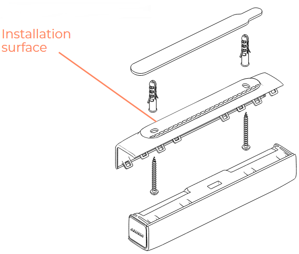
- Verify installation surface suitable for chosen mounting method
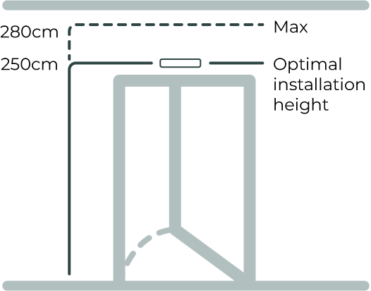
Planning Sensor Placement
Key Considerations:
- Maximum passageway width: 1600mm (1.6 meters)
- Maximum passageway height: 2800mm (2.8 meters)
- Recommended installation height: 2500mm from floor
- Direction configuration: Determined during installation (which side is “entry”)
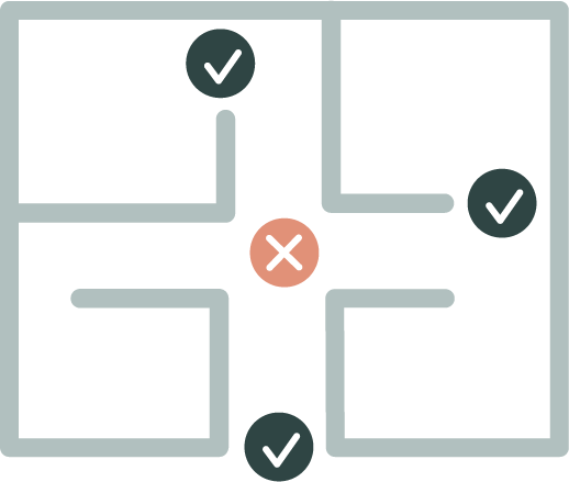
Passageway Suitability
Ideal passageways:
- Interior doorways (office-to-lobby, hallway-to-meeting room)
- Corridor bottlenecks (natural traffic flow points)
- Passage points between functionally distinct spaces
- Doorframes guiding people through defined path
Unsuitable locations:
- Wide-open entry zones (people side-by-side)
- Areas where people change direction abruptly
- Spaces where people linger unpredictably
Network Coverage Planning
- Maximum distance: 20m between sensors or to gateway
- Use intermediate sensors as routers for distances > 20m
- ENTRYWAY sensors work indoors only (0-50°C, 8-90% RH)
- Plan mesh topology for reliable data transmission
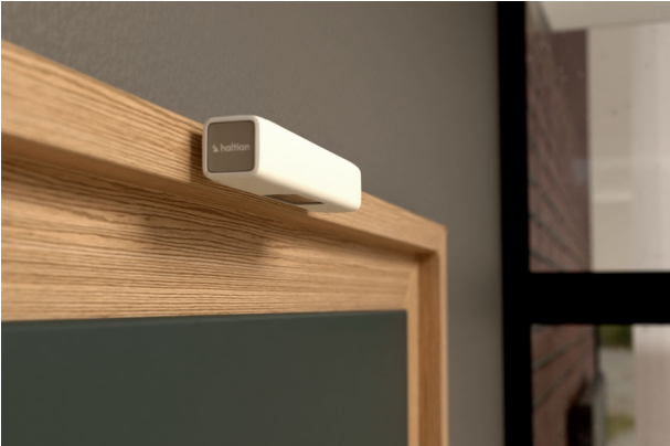
Installation Method 1: Top of Doorframe
Most common and recommended installation method
Requirements
- Location: Middle of doorframe
- Position: Device flush with bottom edge of doorframe
- Clearance: No more than 1 cm above bottom surface
- Detection area: At least 10 cm from device to top of detection zone
- Door consideration: Opposite side from door swing (avoid detecting door movement)
Step-by-Step Installation
1. Select Installation Position
- Identify center of doorframe (width-wise)
- Ensure doorframe at least 2200mm high (2500mm recommended)
- Verify doorframe width ≤ 1600mm
- Check door opens away from sensor side
2. Mark Mounting Position
- Hold sensor at center of doorframe
- Bottom of sensor flush with bottom edge of doorframe (or max 1 cm above)
- Sensor oriented so Haltian logo is on left side (default entry direction)
- Mark screw holes or tape position with pencil
3. Prepare Surface
For screw mounting:
- Drill pilot holes at marked positions
- For concrete/brick: Insert screw anchors
- For wood: Pilot holes sufficient
For tape mounting:
- Clean surface thoroughly (alcohol wipe recommended)
- Ensure surface dry and dust-free
- Temperature > 10°C for tape adhesion
4. Mount Sensor
Screw mounting (permanent):
- Align sensor with pilot holes
- Insert screws through mounting holes in C-cover
- Tighten securely (do not over-tighten - plastic housing)
- Verify sensor level and flush with doorframe bottom
Tape mounting (semi-permanent):
- Peel backing from mounting tape (included in package)
- Apply tape to C-cover mounting surface
- Press sensor firmly against doorframe
- Hold for 30 seconds
- Wait 24 hours for full tape adhesion before activation
5. Configure Entry Direction
Default configuration:
- Entry direction: Towards sensor when Haltian logo is on left side
- Exit direction: Away from sensor
If different direction needed:
- Note sensor orientation during installation
- Contact Haltian support after installation with sensor ID and desired entry direction
- Haltian configures remotely via Haltian IoT
6. Verify Installation
- Sensor flush with doorframe bottom (max 1 cm gap)
- Sensor centered (equal distance from both sides of doorframe)
- Detection area clear (no lights, equipment on wall beneath sensor)
- Door does not interfere with sensor when opening/closing
Doorframe Installation Best Practices
✅ Do:
- Center sensor width-wise on doorframe
- Install on side opposite door swing
- Ensure flush alignment with doorframe bottom
- Verify clear detection zone (10 cm minimum clearance beneath sensor)
❌ Avoid:
- Installing on side where door opens (door motion interferes)
- Gaps > 1 cm between sensor and doorframe bottom
- Locations with equipment/lights directly beneath sensor
- Uneven or unstable doorframes
Installation Method 2: Ceiling Installation
Ideal for hallways and corridors without doorframes
Requirements
- Location: Middle of hallway ceiling
- Corridor width: Maximum 1600mm (1.6 meters)
- Ceiling height: 2200-2800mm recommended
- Foot traffic: Consider general traffic direction
Step-by-Step Installation
1. Select Installation Position
- Identify center of corridor (width-wise)
- Choose position with predictable foot traffic flow
- Measure ceiling height (should be 2200-2800mm)
- Verify corridor width ≤ 1600mm
2. Mark Mounting Position
- Mark center point on ceiling
- Sensor orientation: Haltian logo on left for default entry direction
- Mark screw holes or tape position
3. Prepare Ceiling Surface
For screw mounting:
- Drill pilot holes upward into ceiling
- For concrete ceiling: Use anchors rated for sensor weight (166g + mounting)
- For drywall: Use drywall anchors or toggle bolts
- For drop ceiling: Secure to ceiling tile support or joists
For tape mounting:
- Clean ceiling surface (alcohol wipe)
- Ensure dry and dust-free
- Verify tape rating sufficient for ceiling mounting (included tape suitable)
4. Mount Sensor
Screw mounting (recommended for ceiling):
- Insert screws through C-cover mounting holes
- Align with pilot holes in ceiling
- Tighten securely (sensor weight 166g, minimal load)
- Verify sensor secure and cannot rotate
Tape mounting:
- Apply mounting tape to C-cover
- Press sensor firmly to ceiling
- Hold for 30 seconds
- Use temporary support (e.g., ladder, pole) to maintain pressure for 5 minutes
- Wait 24 hours for full adhesion
5. Configure Entry Direction
- Default: Entry direction when logo on left
- If corridor traffic bidirectional, contact Haltian support to configure preferred entry direction
6. Verify Installation
- Sensor centered on corridor
- Secure mounting (no rotation or sagging)
- Clear line of sight to floor
- Optimal for corridors ≤ 1600mm width
Ceiling Installation Best Practices
✅ Do:
- Use screw mounting for ceilings (more secure than tape)
- Center sensor on corridor width
- Consider typical foot traffic direction
- Verify ceiling height within 2200-2800mm range
❌ Avoid:
- Wide corridors (> 1600mm) - accuracy decreases
- Ceilings > 2800mm - detection unreliable
- Locations with ceiling obstructions (lights, ducts, vents)
Installation Method 3: Side of Doorframe (Horizontal)
Alternative when top-of-doorframe installation not feasible
Requirements
- Location: Side of doorframe (opposite door swing)
- Position: Device flush with bottom edge of doorframe
- Clearance: No more than 1 cm above bottom surface
- Minimum distance: 10 cm from detection area
- Door consideration: Install opposite side from door swing
Step-by-Step Installation
1. Select Installation Position
- Choose side of doorframe opposite door swing
- Measure to ensure bottom edge of sensor flush with bottom edge of doorframe (or max 1 cm above)
- Sensor oriented horizontally (logo on left for default direction)
2. Follow Mounting Steps
- Same as “Top of Doorframe” installation (screw or tape)
- Key difference: Sensor on side of doorframe instead of top
3. Configure Entry Direction
Default operation:
- Entry direction: Towards sensor when Haltian logo on left
- Exit direction: Away from sensor
For non-default directions:
- Contact Haltian support after installation
- Provide sensor ID and desired entry direction
- Haltian configures remotely
4. Verify Installation
- Sensor flush with doorframe bottom (side-mounted)
- No door interference when opening/closing
- Clear detection zone
Side-Mounted Installation Best Practices
✅ Do:
- Install opposite door swing side
- Maintain flush alignment with doorframe bottom
- Verify clear detection path
❌ Avoid:
- Installing on door swing side (interference)
- Locations with equipment beneath sensor
Installation Method 4: Vertical Wall Installation
Used when overhead installation not feasible (high ceilings, no doorframes)
Requirements
- Installation height: 1 meter from floor (optimal)
- Minimum clearance: People must not pass closer than 10 cm from sensor
- Clear field of view: No people at greater distances in detection direction
- Orientation: Vertical on wall surface or door jambs
Step-by-Step Installation
1. Select Installation Position
- Choose wall surface or door jamb
- Measure 1 meter height from floor (optimal)
- Ensure people will pass at least 10 cm away from sensor
- Verify no obstructions in detection direction
2. Mark Mounting Position
- Mark 1-meter height with level line
- Position sensor vertically (oriented upward)
- Mark screw holes or tape position
3. Mount Sensor
Screw mounting:
- Drill pilot holes at marked position
- Insert anchors if needed (concrete/brick)
- Attach sensor with screws
- Verify vertical orientation (use level)
Tape mounting:
- Clean wall surface
- Apply mounting tape
- Press sensor firmly to wall
- Hold 30 seconds, verify vertical alignment
4. Configure Entry Direction
Vertical installation requires configuration:
- Contact Haltian support after installation
- Provide sensor ID and entry direction (based on wall-mounted orientation)
- Haltian configures remotely
5. Verify Installation
- 1-meter height from floor
- Vertical orientation
- People pass at least 10 cm from sensor
- Clear field of view
Vertical Installation Best Practices
✅ Do:
- Mount at 1-meter height (optimal)
- Ensure minimum 10 cm clearance from passing people
- Verify vertical orientation (use level)
- Contact Haltian for direction configuration
❌ Avoid:
- Mounting lower than 1 meter (poor detection angle)
- Locations where people may pass closer than 10 cm
- Horizontal orientation on wall (use doorframe/ceiling methods instead)
Mounting Hardware and Tools
Included in Package
- Haltian ENTRYWAY sensor (with 2× AA batteries installed)
- C-cover (mounting bracket)
- Mounting tape (double-sided adhesive)
- 2× screws
- 2× screw anchors (for concrete/brick)
Additional Tools Needed
For screw mounting:
- Drill (for pilot holes in concrete/brick/wood)
- Appropriate drill bit (size depends on wall material)
- Screwdriver (Phillips or flathead, depending on screw type)
- Level (to ensure sensor alignment)
- Pencil (to mark mounting positions)
For tape mounting:
- Alcohol wipes (to clean surface)
- Level (for alignment)
- Temporary support (for ceiling installations)
For ceiling mounting (additional):
- Drywall anchors or toggle bolts (if drywall ceiling)
- Ladder or lift (for access)
Weatherproofing (Indoor Use Only)
- ENTRYWAY operates indoors only (0-50°C, 8-90% RH)
- No additional weatherproofing needed for indoor installation
- Do not install outdoors (not IP-rated for outdoor use)
Post-Installation Verification
Network Connection
Wait for network join:
- Device automatically joins Wirepas mesh network
- Typical join time: 1-10 minutes
- May take longer in sparse mesh environments
Verify in Haltian IoT Studio:
- Log into IoT Studio portal
- Navigate to device list
- Confirm sensor appears with correct ID
- Check “Last Seen” timestamp
Detection Testing
Baseline Test (Empty)
- Ensure passageway empty (no people in detection zone)
- Observe sensor for 5 minutes (should report no entries/exits)
- Verify LED indicator behavior (check LED patterns in sensor documentation)
Entry Test
- Walk through passageway in entry direction:
- Default: Towards sensor (Haltian logo on left)
- Or configured direction (if custom)
- Complete full passage (walk through all three PIR beam sectors)
- Wait 30 seconds (measurement interval)
- Check IoT Studio for “entries” count increment
Exit Test
- Walk through passageway in exit direction:
- Default: Away from sensor
- Or configured direction (if custom)
- Complete full passage (walk through all three PIR beam sectors)
- Wait 30 seconds (measurement interval)
- Check IoT Studio for “exits” count increment
Directional Verification
- Entry direction test:
- Walk through in entry direction
- Verify “entries” increments, “exits” does not
- Exit direction test:
- Walk through in exit direction
- Verify “exits” increments, “entries” does not
- If incorrect:
- Contact Haltian support to reverse direction configuration
Repeat Testing
- Test 5-10 times to verify consistent detection
- Vary walking speed (slow, normal, fast)
- Test with different people (height, clothing variations)
Signal Strength Check
Review RSSI values in IoT Studio:
- Good signal: > -70 dBm
- Acceptable: -70 to -85 dBm
- Poor: < -85 dBm
If signal poor:
- Add intermediate sensor as router
- Relocate gateway closer
- Check for RF obstructions (metal structures)
Installation Checklist
- Gateway operational and network ready
- Passageway width ≤ 1600mm
- Passageway height 2200-2800mm (2500mm recommended)
- Installation method selected (doorframe/ceiling/side/vertical)
- Surface prepared (drilled, anchors installed, or cleaned for tape)
- Sensor securely mounted
- Sensor alignment verified (level, centered, flush as required)
- Entry direction configured (default or custom via Haltian support)
- Device appears in IoT Studio
- Empty state verified (no false detections)
- Entry direction verified (walking through increments “entries”)
- Exit direction verified (walking through increments “exits”)
- Signal strength acceptable (RSSI > -85 dBm)
- No obstructions beneath sensor (lights, equipment)
- Door (if present) does not interfere with sensor
- Documentation updated (location, sensor ID, configuration)
Common Installation Mistakes
Mistake 1: Passageway Too Wide
Problem: Passageway > 1600mm width
Impact: Detection accuracy decreases, multiple people side-by-side cause missed counts
Solution: Choose narrower passageways, or install multiple sensors for wider entrances
Mistake 2: Installing on Door Swing Side
Problem: Sensor detects door movement or door pump mechanism
Impact: False entry/exit counts from door motion
Solution: Install on opposite side from door swing
Mistake 3: Gap Between Sensor and Doorframe Bottom
Problem: Sensor > 1 cm above doorframe bottom edge
Impact: Detection zone incorrect, reduced accuracy
Solution: Ensure sensor flush with doorframe bottom (max 1 cm gap)
Mistake 4: Equipment Beneath Sensor
Problem: Lights, thermostats, or other devices installed on wall beneath sensor
Impact: Heat from equipment interferes with thermal detection (3-PIR sensors detect heat)
Solution: Clear all equipment from wall beneath sensor (minimum 10 cm clearance)
Mistake 5: Incorrect Entry Direction
Problem: Entry direction configured opposite to actual traffic flow
Impact: Entries counted as exits and vice versa
Solution: Verify direction during testing, contact Haltian support to reverse if needed