Installation
Physical Installation
Mounting Options
The Gateway N8 supports multiple mounting configurations for different deployment scenarios.
Wall Mounting
Mark Mounting Points
- Use mounting holes on rear panel as template
- Spacing: 100mm horizontal, 60mm vertical
- Ensure surface can support 500g load
Install Mounting Screws
- Use 2 x M4 screws (not included)
- Drill pilot holes for drywall/wood installations
- Leave 2-3mm gap for mounting slots
Secure Gateway
- Align mounting slots with screw heads
- Slide gateway down to lock in place
- Verify secure mounting before cable connection
Desktop Placement
- Place on flat, stable surface
- Ensure adequate ventilation (10cm clearance on all sides)
- Position away from heat sources and direct sunlight
Dimensional Requirements
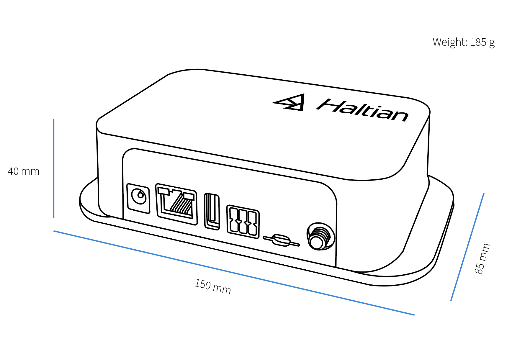
- Dimensions: 150 x 85 x 40mm (W x H x D)
- Clearance Required: 10cm on all sides for ventilation
- Cable Bend Radius: Minimum 25mm for Ethernet/power cables
Power Connection
BLE Version
DC Power (Recommended):
- Connect 9-36V DC power supply to DC jack
- Ensure correct polarity (center positive)
- Use twist & lock feature to secure connector
- Power LED illuminates immediately
Connector Specifications:
- Outer diameter: 5.5mm
- Inner diameter: 2.1mm
- Center pin: Positive (+)
- Outer barrel: Negative (-)
Power over Ethernet (Alternative):
- Connect PoE-capable Ethernet switch to RJ45 port
- Verify PoE standard: IEEE 802.3af (15.4W) or 802.3at (25.5W)
- Power LED should illuminate within 5 seconds
- Gateway boots automatically (30-60 seconds)
LTE Version (DC Only)
The LTE version does NOT support PoE. Use DC power only.
Select Power Supply
- Voltage: 9-36V DC
- Minimum current: 1A @ 12V (2A recommended)
- Use regulated power supply for best performance
Connect DC Power
- Insert DC jack into power port
- Rotate connector clockwise to lock
- Verify LED illumination
Verify Power Consumption
- Idle: 0.4W (LED only)
- Typical operation: 3-5W
- Peak (LTE transmission): 8W max
Network Connection
Ethernet Setup
For Fixed Network Installations:
Connect Ethernet Cable
- Use Cat5e or Cat6 cable
- Maximum length: 100m
- Connect to Gigabit switch for best performance
Verify Network Configuration
- Gateway obtains IP via DHCP by default
- Check switch port LED for link status
- Gateway attempts cloud connection within 60 seconds
Network Requirements
- DHCP server on network (for automatic IP)
- Outbound MQTT over TLS (port 8883) allowed
- Outbound HTTPS (port 443) allowed
- NTP access (port 123) for time synchronization
- DNS resolution available
Firewall Configuration
The gateway requires outbound access to Haltian IoT cloud services. Configure your firewall to allow the following traffic:
Required Outbound Ports:
| Port | Protocol | Direction | Purpose |
|---|---|---|---|
| 8883 | TCP | Outbound | MQTT over TLS — gateway cloud connection |
| 443 | TCP | Outbound | HTTPS — provisioning and firmware updates |
| 123 | UDP | Outbound | NTP — time synchronization |
IP Records:
| Host | Port | Protocol | Direction | Purpose |
|---|---|---|---|---|
| DNS servers (per DHCP or static config) | 53 | UDP/TCP | Outbound | DNS service |
Customer-specific FQDN endpoints are provided by Haltian during onboarding. Contact support@haltian.com if you need the exact hostnames for your firewall rules.
LTE Setup (LTE Version Only)
For Cellular Backhaul:
Connect LTE Antenna
- Attach external LTE antenna to SMA connector
- Hand-tighten (do not over-torque)
- Position antenna vertically for optimal reception
Verify Cellular Connection
- LTE LED indicates connection status
- Gateway will connect to cellular network automatically
- Fallback to 3G/2G if LTE unavailable
LTE Bands Supported:
- LTE Cat 4: Check regional specifications
- 3G/2G fallback: Worldwide coverage
Initial Verification
LED Status Indicators
Monitor LEDs for system status:
| LED Pattern | Meaning | Action |
|---|---|---|
| Solid Green | Power on, normal operation | None required |
| Blinking Green | Network activity | Normal operation |
| No LED | No power | Check power connection |
Cloud Registration
Verify Gateway Registration:
Access Haltian IoT Studio
- Log in to your Haltian IoT account
- Navigate to Devices → Gateways
Locate New Gateway
- Gateway appears automatically after cloud connection
- Note gateway UUID for identification
Verify Network Connectivity
- Check “Last Seen” timestamp (should be recent)
Initial Configuration
After successful registration:
- Set Gateway Name - Assign meaningful name (location, function)
- Deploy Sensors - Position sensors within range
- Monitor Network Formation - Verify sensors join mesh network
Cable Management
Best Practices
- Ethernet: Avoid sharp bends, maintain minimum 25mm radius
- Power: Route away from high-voltage lines (>100V AC)
- LTE Antenna: Position for best signal, avoid metal obstructions
- Cable Length: Keep Ethernet under 100m, minimize power cable length
Environmental Considerations
- Operating Temperature: 0°C to 50°C
- Humidity: 0% to 95% RH (non-condensing)
- Ventilation: Ensure air circulation around enclosure
- Protection: IP rating suitable for indoor use only
Post-Installation Checklist
- Gateway physically secured (wall/desktop)
- Power connected and LED illuminated
- Network cable connected (Ethernet)
- LTE antenna connected (LTE version)
- Gateway appears in Haltian IoT Studio
- Gateway named appropriately
- Network connectivity verified
Next Steps
- Configure Network - Set up network parameters
- Deploy Sensors - Position sensors and verify connectivity
- Monitor Network - Check mesh network performance