Installation
Before Installation
Prerequisites
- Ensure Thingsee Gateway is installed and operational
- Plan sensor locations to maintain mesh network coverage (< 20m between nodes)
- Identify monitoring zones (parking spaces or loading docks)
- Determine optimal mounting position (wall, pole, or ceiling)
- Verify mounting surface suitable for chosen method
Planning Sensor Placement
Key Considerations:
- Sensor beam must be directed toward monitored area
- Adjust sensing distance to avoid detecting beyond intended zone
- Install perpendicular to center of measured area for best performance
- Can be angled up to 45° depending on installation spot
Network Coverage Planning
- Maximum distance: 20m between sensors or to gateway
- Use intermediate sensors as routers for distances > 20m
- RADAR sensors work outdoors - plan for weather exposure
- IP68 rating allows installation in exposed locations
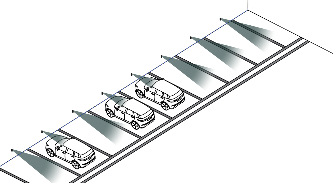
Parking Space Monitoring - Wall or Pole Mount
Most common installation method for parking
Installation Height
- Recommended: 40-60 cm from floor (knee height)
- Optimal placement: Middle of parking slot
- Beam direction: Perpendicular to parking space
Wall/Pole Mounting Steps
Select mounting location:
- Middle of parking slot (width-wise)
- 40-60 cm height from floor
- On wall or pole adjacent to parking space
- Ensure beam points into parking space
Mark mounting position:
- Hold sensor at desired location
- Verify beam direction covers entire parking space
- Mark screw/bolt holes with pencil
- Check for obstructions in sensing cone
Prepare mounting surface:
- For concrete/brick: Drill holes, insert anchors
- For metal pole: Use pole mounting bracket (if available)
- For wood: Pilot holes recommended
- Clean mounting area
Mount sensor:
- Align sensor with marked positions
- Insert screws/bolts through mounting holes
- Tighten securely (do not over-tighten)
- Verify sensor level and beam direction correct
Verify orientation:
- Sensor face directed at parking space
- 17-degree cone covers full space
- No obstructions in sensing path
- Test: Place object in space, verify detection
Placement Best Practices
✅ Good placement:
- Center of parking slot
- Clear line of sight to vehicle detection point
- Perpendicular to parking space
- Protected from vehicle impacts (set back from edge)
❌ Avoid:
- Mounting where vehicles might strike sensor
- Locations with obstructions (poles, signs) in sensing cone
- Areas where water pools or drains (though IP68 rated)
- Direct exposure to vehicle headlights (if possible)
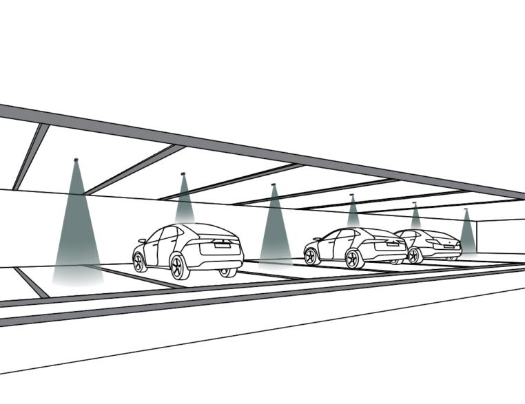
Parking Space Monitoring - Ceiling Mount
Recommended for covered parking or indoor garages
Installation Height and Position
- Mount: Directly above parking space
- Beam direction: Downward toward parking surface
- Height: Varies based on ceiling height (sensing range 10 cm - 10 m)
- Optimal: 2-5 meters above parking surface
Ceiling Mounting Steps
Locate optimal position:
- Center of parking space (lengthwise and width-wise)
- Verify ceiling height within sensor range (< 10m)
- Check for ceiling obstructions (pipes, ducts, lights)
- Mark position on ceiling
Prepare ceiling mount:
- For drop ceiling: Use tile support or bracket
- For concrete ceiling: Drill holes, insert anchors
- For drywall: Use appropriate anchors rated for sensor weight (166g)
- Ensure mount can support sensor securely
Install sensor:
- Attach sensor to ceiling mount
- Sensor face pointing downward
- Tighten securely
- Verify sensor cannot rotate or fall
Adjust sensing distance:
- Configure for ceiling height + vehicle height
- Account for different vehicle types (cars vs. SUVs)
- Test with vehicle present and absent
- Fine-tune distance setting if needed
Ceiling Installation Considerations
- Covered parking: Ideal use case
- Indoor garages: Excellent reliability
- High ceilings: May approach 10m range limit - test carefully
- Lighting: Avoid mounting directly adjacent to bright lights (not a technical issue, but for maintenance access)
Loading Dock Monitoring
Optimized for detecting trucks/trailers at loading bays
Installation Position
- Front of dock: Monitor approaching vehicles
- Above dock door: Detect when trailer backs in
- Side of dock: Monitor dock occupancy
- Sensing distance: Typically 5 meters (default loading dock config)
Installation Steps
Select mounting point:
- Wall or pole near loading dock
- Height: 1-3 meters (depending on what you’re detecting)
- Beam directed toward approach path or docking position
- Consider trailer height and positioning
Configure sensing distance:
- Default loading dock: 5 meters
- Adjust based on dock depth and trailer size
- Avoid detecting beyond dock area (e.g., passing vehicles)
- Test with trailer in position
Mount sensor:
- Follow wall/pole mounting steps (see Parking section)
- Ensure secure mounting (loading docks are high-vibration environments)
- Protect from vehicle strikes (set back or use protective barrier)
- Verify IP68 seal intact
Test detection:
- Empty dock: Should show unoccupied
- Trailer backed in: Should show occupied
- Adjust distance if needed
- Verify no false positives from passing vehicles
Loading Dock Best Practices
✅ Optimal:
- Mount to detect trailer at docking position
- Sensing distance set to dock depth
- Protected from vehicle impacts
- Weatherproof (outdoor exposure common)
❌ Avoid:
- Mounting in vehicle impact zone
- Detecting beyond intended dock area
- Locations with heavy vibration (though MIL-STD-810H rated)
Sensing Distance Configuration
Critical for accurate detection
Understanding Sensing Range
- Full range: 10 cm - 10 m
- Parking default: 2 meters
- Loading dock default: 5 meters
- Configurable: Remotely via Haltian Operations Cloud
Setting Appropriate Distance
Parking Spaces
- Compact cars: 1.5-2 meters
- Standard cars: 2 meters (default)
- SUVs/Trucks: 2.5-3 meters
- Mixed use: 2 meters (covers most vehicles)
Loading Docks
- Shallow docks: 3-4 meters
- Standard docks: 5 meters (default)
- Deep docks: 6-8 meters
- Approach detection: 8-10 meters
Avoiding False Positives
Set distance to:
- Cover full monitored area
- Stop before adjacent areas
- Exclude passing traffic
- Account for vehicle variations
Example: Parking space depth 5m, but adjacent walkway 6m away. Set sensing distance to 5m to avoid detecting pedestrians.
Mounting Hardware
Included in Package
- RADAR sensor unit
- Mounting bracket (check package)
- Installation guide
Additional Hardware Needed
For wall/concrete mounting:
- Screws or bolts (M6 or M8 recommended)
- Wall anchors for concrete/brick
- Drill and appropriate drill bit
- Level (for alignment)
For pole mounting:
- Pole mounting bracket (if not included, contact Haltian)
- U-bolts or hose clamps (for round poles)
- Stainless steel hardware (outdoor use)
For ceiling mounting:
- Ceiling mount bracket
- Appropriate anchors for ceiling type
- Ladder or lift for access
Weatherproofing (Already IP68)
- Sensor is IP68 rated (no additional weatherproofing needed)
- Ensure mounting bracket drainage (water doesn’t pool on bracket)
- Verify mounting hardware corrosion-resistant (stainless steel recommended)
Post-Installation Verification
Network Connection
Wait for network join:
- Device automatically joins Wirepas mesh network
- Typical join time: 1-10 minutes
- May take longer in outdoor environments with sparse mesh
Verify in Haltian IoT Studio:
- Log into IoT Studio portal
- Navigate to device list
- Confirm sensor appears with correct ID
- Check “Last Seen” timestamp
Detection Testing
Baseline test (empty):
- Ensure parking space or dock is empty
- Verify sensor reports “unoccupied”
- Wait 5-10 minutes for stable reading
Occupancy test:
- Park vehicle in space (or position trailer at dock)
- Wait 30-60 seconds (depending on measurement interval)
- Verify sensor reports “occupied” in IoT Studio
Exit test:
- Remove vehicle
- Wait 30-60 seconds
- Verify sensor returns to “unoccupied”
Repeat several times to confirm consistent detection
Signal Strength Check
Review RSSI values in IoT Studio:
- Good signal: > -70 dBm
- Acceptable: -70 to -85 dBm
- Poor: < -85 dBm
If signal poor:
- Add intermediate sensor as router
- Relocate gateway closer (if possible)
- Check for RF obstructions (metal structures)
Sensing Distance Verification
- Measure actual distance from sensor to vehicle detection point
- Compare to configured distance in IoT Studio
- Adjust if needed (contact Haltian support for remote adjustment)
- Test edge cases:
- Small cars (compact vehicles)
- Large vehicles (SUVs, trucks)
- Verify both detected reliably
Installation Checklist
- Gateway operational and network ready
- Sensor location planned (parking or loading dock)
- Mounting method selected (wall, pole, ceiling)
- Mounting surface prepared (drilled, anchors installed)
- Sensor securely mounted
- Beam direction verified (perpendicular to monitored area)
- Sensor level and aligned
- Device appears in IoT Studio
- Empty state verified (“unoccupied”)
- Occupied state verified (vehicle present)
- Exit verified (vehicle removed, returns to “unoccupied”)
- Signal strength acceptable (RSSI > -85 dBm)
- Sensing distance appropriate for use case
- No false positives from adjacent areas
- Documentation updated (location, sensor ID, configuration)
Support
For installation assistance:
- Email: support@haltian.com
- Remote configuration: Contact for sensing distance adjustments
- Technical support: Site-specific installation questions
- Mesh network planning: Contact for large deployments